
Precision CNC machining is not proved by a small positioning number on a specification sheet; a machine can hit that number and still make a bad part. The drawing may reference the wrong datum, the fixture may distort a thin wall, a warm spindle may drift, a worn tool may push a bore, or the inspection method may disagree with the way the feature functions. Precision is the result of the whole chain, not one machine label.
That distinction separates this guide from our buyer’s guide to precision machining services. The buyer’s guide asks which supplier deserves the order. This article asks how the process actually creates, controls, and verifies accuracy once the order reaches the floor.
We will follow the part from design definition through CAM, setup, cutting, thermal control, tool management, and metrology. The goal is practical: specify only the precision the function needs, select a process that can hold it, and build an inspection plan that proves the result without turning every dimension into a laboratory exercise.
Direct answer — What is precision CNC machining?
Precision CNC machining is a controlled subtractive process that uses computer-programmed machine tools to make parts to defined dimensional, geometric, and surface requirements. CAD geometry is converted into CAM toolpaths and G-code; fixtures locate the work, cutting tools remove material, and probing or inspection verifies critical features. Repeatability comes from controlling datums, setups, temperature, tool wear, material behavior, and measurement uncertainty across the production run.
Key Takeaways
- Precision begins on the drawing. A tight number without a functional datum, measurement method, or clear acceptance rule creates disagreement, not accuracy.
- Every setup transfers the part into a new coordinate system. Good workholding and fewer datum transfers often matter more than another decimal place in machine positioning.
- Heat, tool wear, cutting force, material stress, and chip control move the process during a run. The first good part does not prove the hundredth will be good.
- Dimensional tolerance, GD&T, and surface roughness describe different properties. They need different controls and, often, different instruments.
- Inspection is part of process design. The gage, fixturing, environment, sampling plan, and measurement uncertainty must fit the feature being accepted.
How precision CNC machining works
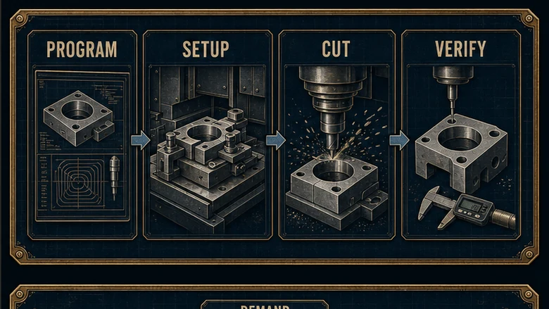
Precision CNC machining starts with product definition. A 3D CAD model carries nominal geometry. A controlled drawing or model-based definition carries dimensions, datums, geometric controls, finish, material, and notes. CAM software then creates toolpaths, chooses cutting motions, and posts those motions as G-code for a specific machine and control.
The machine follows coordinates, feeds, spindle commands, tool changes, coolant commands, and probing cycles. It does not understand why a bore aligns a bearing or why one face seals. That intent must be translated into datums, tolerances, process sequence, and inspection. ASME Y14.5 establishes the shared language for dimensioning and geometric tolerancing, so design, machining, and inspection interpret the same requirement.
Most parts pass through roughing and finishing. Roughing removes material quickly while leaving controlled stock. Semi-finishing stabilizes geometry and prepares critical surfaces. Finishing uses the final tool, path, offsets, and cutting conditions to bring features into tolerance and produce the required surface. Some features then move to grinding, honing, lapping, EDM, or another finishing process because milling or turning is not the best final control.
Precision is an error budget
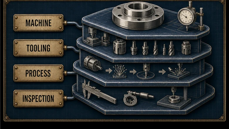
Every real process has variation. Machine geometry, servo behavior, spindle growth, tool runout, tool deflection, insert wear, fixture compliance, cutting force, material stress, coolant temperature, room temperature, burrs, and measurement all contribute. The part meets print when their combined effect stays inside the functional tolerance.
This is where precision work meets lean manufacturing: stability and standard work come before optimization. A repeatable setup, controlled tool assembly, clean locating surfaces, known warm-up routine, and clear reaction plan remove more variation than heroic inspection at the end.
Machine condition belongs in the same error budget. Backlash, worn way surfaces, spindle damage, poor lubrication, and dirty coolant can change size or finish long before the machine stops. A targeted preventive maintenance system should schedule geometry checks, spindle and lubrication work, coolant control, probe calibration, and other tasks tied to part quality, not only breakdown avoidance.
NIST’s 2026 research on in-process measurement of machine-tool thermal deformation describes how motor heat, cutting heat, and ambient changes can affect volumetric error and part quality. The lesson for a normal shop is not that every machine needs an optical compensation system. It is that temperature is a process input, so warm-up, coolant control, cycle pattern, and inspection timing cannot be left to chance on tight work.
| Error source | What moves | Common control |
|---|---|---|
| Datum and setup transfer | Feature location and orientation | Functional datums, fewer setups, probing, qualified fixtures |
| Thermal drift | Machine geometry, tool length, workpiece size | Warm-up, stable cycle, coolant control, environmental limits, offsets |
| Tool wear and runout | Diameter, form, finish, cutting force | Preset tools, life limits, sister tools, in-process checks, wear offsets |
| Workholding force | Thin walls, roundness, flatness | Support at functional points, controlled clamping, soft jaws, process stock |
| Material stress | Shape after stock removal or heat treatment | Stable condition, balanced roughing, stress relief, rest and re-clamp steps |
| Measurement system | Reported result and accept/reject decision | Suitable gage, calibration, method, environment, uncertainty review |
Choose the process around the geometry
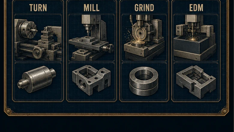
“CNC” describes the control, not one cutting process. A prismatic housing, a long small-diameter pin, a hardened bore, and a sharp internal corner need different machine architectures and finishing routes. Select the process that makes the critical geometry natural.
| Process | Natural geometry | Precision advantage | Watch for |
|---|---|---|---|
| 3-axis milling | Prismatic parts, pockets, planar faces | Rigid, accessible, economical for features on a few orientations | Extra setups for side features and datum transfer |
| 5-axis milling | Compound angles, impellers, complex housings | Reaches multiple faces in one clamping and reduces transfers | Post, kinematic calibration, tool-center-point error, access |
| CNC turning | Shafts, bores, shoulders, threads | Part rotation makes concentric geometry natural | Slender-part deflection, chuck distortion, bar variation |
| Swiss machining | Long, small-diameter, high-volume parts | Guide bushing supports stock close to the cut | Material straightness, bushing fit, process complexity |
| Grinding | Hardened surfaces, bearing fits, finish-critical diameters | Fine size and surface control after heat treatment | Burn, residual stress, wheel condition, dressing |
| Wire or sinker EDM | Hard materials, narrow features, internal forms | No conventional cutting force on the workpiece | Recast layer, electrode/wire path, slower removal |
A multi-axis machine can reduce setup error, but one setup is not always one operation. The program may still need roughing, rest machining, probing, tool changes, and a second clamping to finish the holding surfaces. Map which datums are created, used, and transferred at each stage.
Material changes the process window
Material affects cutting force, heat flow, tool wear, burr formation, residual stress, and dimensional stability. Two alloys with similar strength can behave very differently under the cutter. The drawing should name the grade and condition, because “aluminum” or “stainless” is not a process specification.
| Material family | Machining behavior | Precision concern |
|---|---|---|
| Aluminum alloys | Generally machinable with high removal rates | Thin-wall distortion, burrs, thermal expansion, soft-jaw marking |
| Stainless steels | Higher cutting force; some grades work-harden | Heat, tool wear, built-up edge, distortion after heavy removal |
| Titanium alloys | Low thermal conductivity concentrates heat near the cut | Tool life, chatter, surface integrity, springback, fire-safe chip control |
| Tool and hardened steels | High hardness may shift finishing to grinding or EDM | Heat-treatment movement, grinding burn, final stock allowance |
| Engineering plastics | Low stiffness and different thermal/moisture behavior | Clamping distortion, heat, creep, burrs, conditioning before measurement |
Metalworking fluid carries heat, lubricates the contact, protects against corrosion, and helps move chips. OSHA’s metalworking-fluid guidance explains those functions and the exposure controls required around mists and contact. In process terms, concentration, delivery, filtration, contamination, and temperature can affect both tool life and finish, so coolant condition needs a standard and a reaction limit.
Dimensional tolerance, GD&T, and surface finish are different
A dimensional tolerance controls size or location around a nominal value. GD&T controls characteristics such as flatness, perpendicularity, position, profile, and runout relative to functional datums. Surface texture describes the small-scale topography left by the process. A part can meet size and fail position, or meet both and fail a sealing finish.
The drawing should tighten only the features that drive fit, motion, sealing, alignment, fatigue, or safety. Blanket tight tolerances add slow finishing passes, extra checks, environmental sensitivity, and scrap risk to features that may not affect function. Tolerance is a design allocation, not a badge of quality.
| Requirement | Question it answers | Typical verification |
|---|---|---|
| Size tolerance | Is this diameter, width, or thickness within limits? | Micrometer, bore gage, air gage, calibrated hand gage, CMM |
| Position or profile | Is the feature located and shaped correctly from its datums? | CMM, vision system, functional gage, specialized fixture |
| Flatness or straightness | Does the surface or axis stay within its form zone? | CMM, indicator and surface plate, optical method |
| Runout | How much does a surface vary as the part rotates on a datum axis? | Indicator fixture, roundness system, CMM where suitable |
| Surface roughness | What microtexture will a seal, bearing, coating, or contact see? | Stylus or optical profilometer with stated parameter and cutoff |
NIST’s surface-roughness calibration work distinguishes parameters such as Ra, Rq, Rz, and Rt and documents uncertainty for them. Calling out “smooth” is therefore not enough. State the parameter, value, units, evaluation length or applicable standard, and which surfaces carry the requirement.
Control the run, not only the first part
The first-article inspection proves that the planned route can produce a conforming sample. Production control proves the route stays capable. Identify critical-to-quality features, decide when they are measured, define tool-life or offset rules, and write the reaction plan before the run starts. A quality management system can hold inspection plans, nonconformances, approvals, and corrective actions, but software cannot repair an ambiguous datum or an unsuitable gage.
Plotting a critical diameter or position over time can reveal a steady wear trend, a warm-up shift, or a sudden special cause. That is the job of statistical process control charts: separate normal process variation from a change that needs investigation. Do not treat every near-limit result as an instruction to chase the offset; over-adjustment can add variation.
Machine utilization also needs context. A spindle can post strong overall equipment effectiveness while producing unstable critical features, and an extra in-process check can lower apparent speed while preventing an expensive lot escape. Quality rate, capability, and delivery matter together.
Build an inspection plan that can answer the drawing
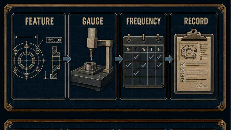
Start feature by feature. What characteristic is controlled? Which datums establish the part? What instrument can access the feature? What is the instrument’s range and resolution? How will the part be supported? Does temperature or conditioning matter? How much measurement uncertainty is acceptable relative to the tolerance and decision risk?
A coordinate measuring machine is flexible for three-dimensional relationships, but it is not automatically the best or fastest choice for every feature. Fixed gages can be more repeatable at the line. Air gages suit tight bores. Profilometers measure surface texture. Optical and machine vision systems can inspect visible geometry quickly when fixturing, lighting, lens, and calibration are controlled.
Measurement results need traceability to the part, lot, drawing revision, program revision, instrument, and disposition.
NIST’s CMM work emphasizes task-specific measurement uncertainty. The useful question is not “Is the CMM calibrated?” but “Can this method, on this feature, in this setup and environment, support the accept/reject decision?” That question belongs in inspection planning before the part reaches final inspection.
| Inspection stage | Purpose | Typical output |
|---|---|---|
| Setup verification | Confirm work offset, fixture, stock, tool and program revision | Setup checklist and probe result |
| In-process check | Catch drift while correction is still possible | Probe value, hand-gage result, wear offset record |
| First article | Validate the planned route and complete requirements | Ballooned drawing and dimensional report |
| Production sampling | Monitor stable features at a risk-based frequency | Control chart, inspection log, capability evidence |
| Final acceptance | Confirm shipment and documentation requirements | Lot report, material certificate, CoC, release record |
Design choices that make precision easier
- Use functional datums. Locate features from the surfaces that establish the part in assembly and can be repeated in manufacturing and inspection.
- Tighten selectively. Reserve narrow limits and fine finish for features whose function needs them.
- Give tools access. Deep narrow pockets, tiny internal radii, and long-reach features increase deflection and force special tooling.
- Support thin geometry. Thin walls and rings move under clamping and cutting force; allow stable holding and a balanced removal sequence.
- Define edge condition. “Break sharp edges” may be acceptable for a bracket and unacceptable for a sealing land or precision interface.
- Plan post-process movement. Heat treatment, plating, anodizing, passivation, and grinding can change size or require process allowance.
When a tolerance is difficult, run a cross-functional review before release. A short design-for-manufacturability discussion can move a datum, open an irrelevant limit, change a corner radius, add grinding stock, or make inspection possible. The best precision process is the one that makes the functional requirement repeatable, not the one that rescues an avoidable drawing problem.
Common precision-machining failures
| Symptom | Likely mechanism | First check |
|---|---|---|
| Size walks during the run | Tool wear, thermal drift, offset chasing | Plot result by sequence against tool and temperature history |
| Thin part changes after unclamping | Fixture distortion or residual stress | Measure clamped and free; review support and stock-removal balance |
| Position fails while sizes pass | Datum transfer, fixture location, probe or setup error | Trace datum creation and coordinate transfer through each setup |
| Supplier and customer measurements disagree | Different datum simulation, method, environment, or uncertainty | Compare the full measurement procedure, not only calibration dates |
| Finish degrades before size moves | Tool edge, chatter, built-up edge, coolant or chip problem | Inspect tool, holder, cutting conditions and fluid delivery |
Root-cause work should follow evidence through machine, method, material, measurement, environment, and people. The fishbone, 5 Whys, Pareto, and FMEA tools in our Six Sigma toolkit help structure that investigation, but the answer still has to be confirmed at the process.
Frequently asked questions
Precision CNC machining is computer-controlled material removal performed to defined dimensional, geometric, and surface requirements. CAD geometry becomes CAM toolpaths and G-code; fixtures locate the work; tools cut it; and probing or inspection verifies critical features. Its defining feature is controlled, documented repeatability across the run, not a particular machine brand or universal tolerance.
There is no single accuracy number for every CNC part. Achievable tolerance depends on feature size, geometry, material, machine condition, workholding, number of setups, thermal stability, tool reach, surface requirement, and measurement method. Specify the functional requirement on the drawing and confirm capability for that feature and production quantity rather than accepting a shop-wide marketing claim.
No machine type is most precise for every geometry. Turning naturally controls concentric features, Swiss machines support long small diameters, five-axis mills reduce setup transfers on complex forms, grinding controls hardened surfaces, and EDM creates hard-to-cut internal shapes. The best process makes the critical geometry natural and can measure it with acceptable uncertainty.
Tighter limits shrink the process error budget. They may require a more stable setup, shorter tool reach, controlled temperature, slower finishing passes, special tooling, added probing, more frequent inspection, capable metrology, and a higher scrap contingency. Cost falls when the drawing reserves tight tolerances for features that affect function instead of applying them across the part.
Inspection combines setup checks, in-process measurements, first-article verification, production sampling, and final release. Instruments may include micrometers, bore or air gages, indicators, vision systems, profilometers, functional gages, and CMMs. The plan must define datums, method, environment, sampling, traceability, and measurement uncertainty for each critical feature.
